What is the CAN interface and what makes it so special?
Unless you just missed your car’s last service appointment, you usually do not have to worry a lot about what is going on under the hood of your car – and that is just fine. But why does your car work so smoothly, even though hundreds of components have to communicate with each other? One reason is the CAN interface, which is the essence of safe and reliable data transmission. Learn more about what CAN is and why we use CAN in the first place in this blogpost.
Who needs bus systems?
When the automotive industry was still in its infancy at the beginning of the 20th century, customer needs were also modest. There was no navigation, air conditioning, driver safety or sophisticated engine and emission control systems. Therefore, it was sufficient, for example, to transmit speed data only to the tachometer.
But the technology continued to develop. Soon it was no longer sufficient for only the tachometer to access speed data. Engine control and radio volume were soon linked to speed data as well. This led to a wide variety of components requiring a cable connection to the speed sensor.
When Bosch introduced the CAN bus in the 1980s, more than 2,000 meters of cabling were needed to transmit data within a car. The CAN interface solved this problem and made car manufacturing cheaper and easier.
CAN stands for Controller Area Network and is a bus system. Bus systems enable different components to communicate via one and the same connection. This means that it is no longer necessary to provide a separate connection to the sensor for each component. If instead one integrates a CAN bus, all components that require speed data can use the same line. This is not only much simpler, but also saves space and weight – two important factors in vehicle engineering.

Basic structure of a CAN system
The standardization brought along by the CAN interface also ensures the intercompatibility of components. It has thus become much easier to use components from different manufacturers in the same vehicle – yet another advantage for manufacturers and customers.
What makes CAN so special.
PXI, PCI, ARINC, MIL-STD or LIN: All these are bus systems from measurement technology that make it possible to connect several devices via one line. But one may now ask: What makes the CAN interface so special?
Bosh developed CAN specifically for the automotive industry, which is also its main area of application. During development, the focus was on creating a reliable data transmission system. The reliability mentioned is so high that CAN buses do even find use in medical applications such as MRIs or, with slight modifications, in aviation technology.
The safety mechanisms of the CAN interface are manifold. The way data is transmitted plays a major role here: Two data lines twisted together are always required to transmit CAN signals. While the signal propagates on the one data line, the same signal, but inverted, goes through the other data line. The receiver only measures the difference between the two signals. An external disturbance (such as electromagnetic radiation) changes both signals in the same way, but the difference remains the same. In measurement technology, one calls this common mode suppression. However, the CAN bus can also detect incorrect and incomplete transmissions and repeat them accordingly.
CAN offers a bandwidth of up to 1 Mbit/s which, however, depends on the length of the cable used. There are also some modified and enhanced versions of the CAN interface. These include:
- CAN FD (flexible data rate): Devices can switch between different data rates.
- OBD 2: A vehicle diagnostic system that uses the CAN bus as a physical interface.
- ARINC 825: Data bus for aerospace applications; used, for example, in the AIRBUS A350.
Since adaptive driving assistance systems require more and more bandwidth, modern automotive applications also use FlexRay or Automotive Ethernet. These are again bus systems, but they offer an increased bandwidth.
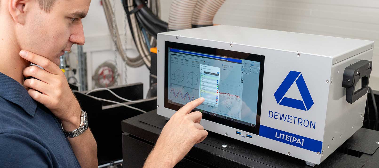
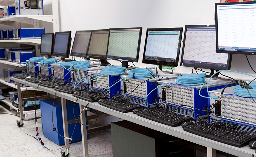
Data analysis with DEWETRON
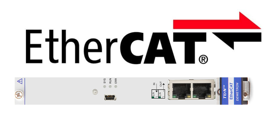
In order to be able to guarantee that various components function correctly and work together properly, it is necessary to analyze the CAN signals of the devices in use. This can be done by using appropriate analog-to-digital converters and interfaces.
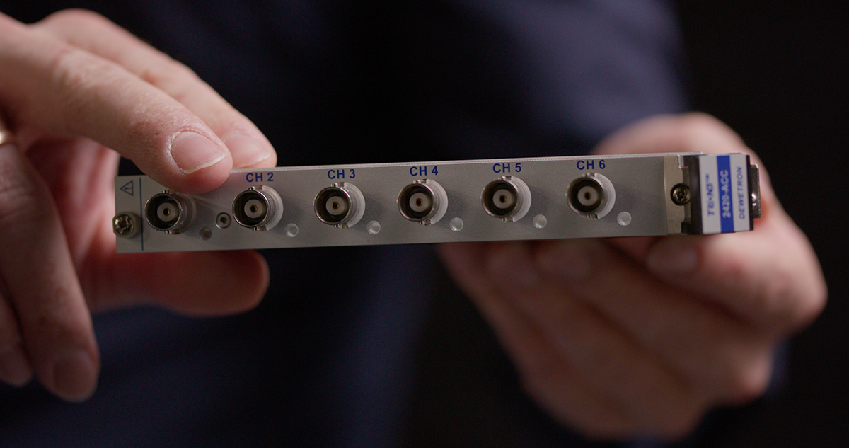
DEWETRON is a specialist in the production of modular and precise measurement systems. For the evaluation and analysis of CAN data we offer our XR modules.