How to do CAN bus data analysis with DEWETRON
This week, we have decided to devote our new article to CAN bus – a popular vehicle bus standard. Keep on reading to find out more about its principles and how DEWETRON helps you to get out the most of it.
The basics behind the CAN bus technology
In short, the purpose of a CAN bus (Controller Area Network) is to enable microcontrollers and other devices to communicate with each other without using a host computer. Although the original intention behind the design was to save copper in the wiring within vehicles, the message-based protocol now finds use in many contexts. As a result of the sophisticated design, the CAN bus prioritizes the messages of each device, even though the data is sequentially transmitted in a frame.
Analyzing CAN bus data with DEWETRON
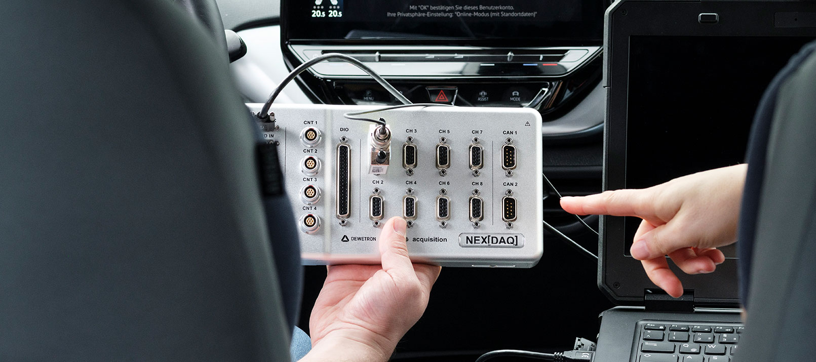
DEWETRON simultaneously analyzes the HV components as well as the communication bus. With our CAN bus interfaces, DEWETRON not only receives and decodes the messages. Apart from that, DEWETRON enables you to also check the voltage and current signal levels of the power train with the highspeed analog input modules. Thanks to DEWETRON’s own measurement software OXYGEN, you can simultaneously record all your data. This includes for instance power groups, motor inputs, RPM, vibration, thermocouple, and CAN bus data. Moreover, you can easily expand your measurement by analyzing CAN-FD or FlexRay data. Apart from that, OXYGEN enables even more features like offline decoding and online data transfer. To achieve the best measurement result, OXYGEN collects all your parameters in only one data file.
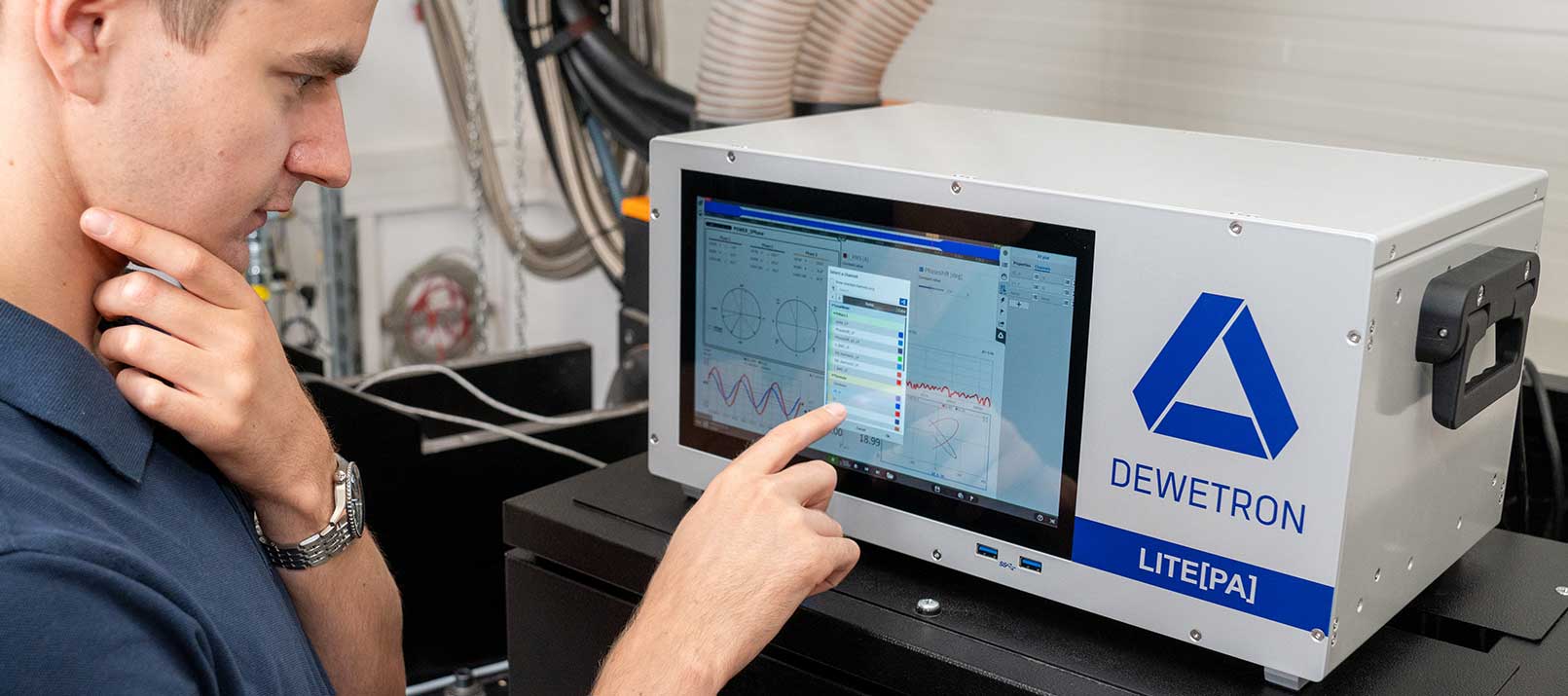
The combination of our DEWE3-PA8 power analyzer chassis, the highspeed signal conditioning modules, and the intuitive measurement software OXYGEN provides you a powerful one-stop solution for all your requirements in just one device.

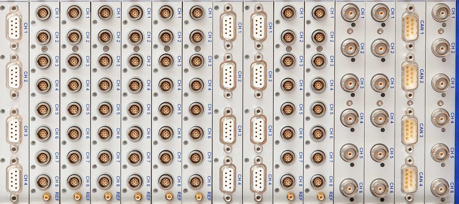
Picture 1: DEWETRON’s power analyzer DEWE3-PA8