What are FIR filters?
In signal processing, filtering is an essential process that removes unwanted components from a signal. One special class of filters are finite impulse response (FIR) filters, which we will discuss in this post in more detail. After a short description of digital filters in general, the structure and function of FIR filters will be discussed. Finally, we give an overview of the implementation of FIR filters in our measurement software OXYGEN.
What are digital filters in general?
A digital filter is a mathematical algorithm for manipulating a signal to extract information and remove unwanted information, such as blocking or passing a certain frequency range. Thus, it is a digital system that converts an input sequence with a transformation process into an output sequence.
There are various different classes of filters. However, based on the length of their impulse response, we can categorize digital filters into the following:
- Infinite impulse response (IIR)
- Finite impulse response (FIR)
Unlike analog filters, which are implemented with electronic components such as capacitors, coils, resistors, etc., digital filters are implemented with logic devices such as ASICs, FPGAs or in the form of a sequential program with a signal processor.
What is the difference between IIR and FIR filters?
In general, IIR and FIR filters differ in their response of a filter to an input impulse. If the impulse response of the filter drops to zero after a finite time has elapsed, it is referred to as an FIR filter (Finite Impulse Response). On the other hand, if the impulse response is unlimited in time, it is an IIR filter (Infinite Impulse Response). Whether the impulse response of a digital filter drops to zero after a finite time depends on how the output values are calculated. With FIR filters, the output values depend only on the current and preceding input values, while with IIR filters the output values depend additionally on the preceding output values.
The advantage of IIR filters over FIR filters is that IIR filters typically require fewer coefficients to perform comparable filtering operations, operate faster, and require less RAM. However, a big disadvantage of IIR filters is their non-linear phase response. For applications that do not require phase information, such as monitoring signal amplitude, IIR filters are well suited. But, for applications that require a linear phase response, FIR filters are generally better suited.
How do FIR filters work?
Fig. 1 demonstrates the functional operation of an FIR filter. At the input, the data/values x(n) are applied by the A/D converter clock by clock (sample by sample).
In the upper row, there are shift elements (z-1) which shift the data/values applied to the input by one step for each clock cycle. This means that at the end of the following example, the value x(n-3) is three clocks prior to the current value x(n). In the center are the FIR coefficients k0 – km. These coefficients represent an amplifier that multiplies the input value by the gain „k“. The bottom row is the summation branch which adds up the results of all multiplications (integration). The output y(n) is now the processed signal according to the FIR coefficients and can be represented by the following mathematical expression:
$$ y(n)=sumlimits_{i = 0}^m k(i)*x(n-i) $$
")
Fig. 1: Calculation process of a FIR filter
In one of our whitepapers, we further present a detailed example of how to determine the filter coefficients of an FIR low-pass filter.
FIR filters in OXYGEN
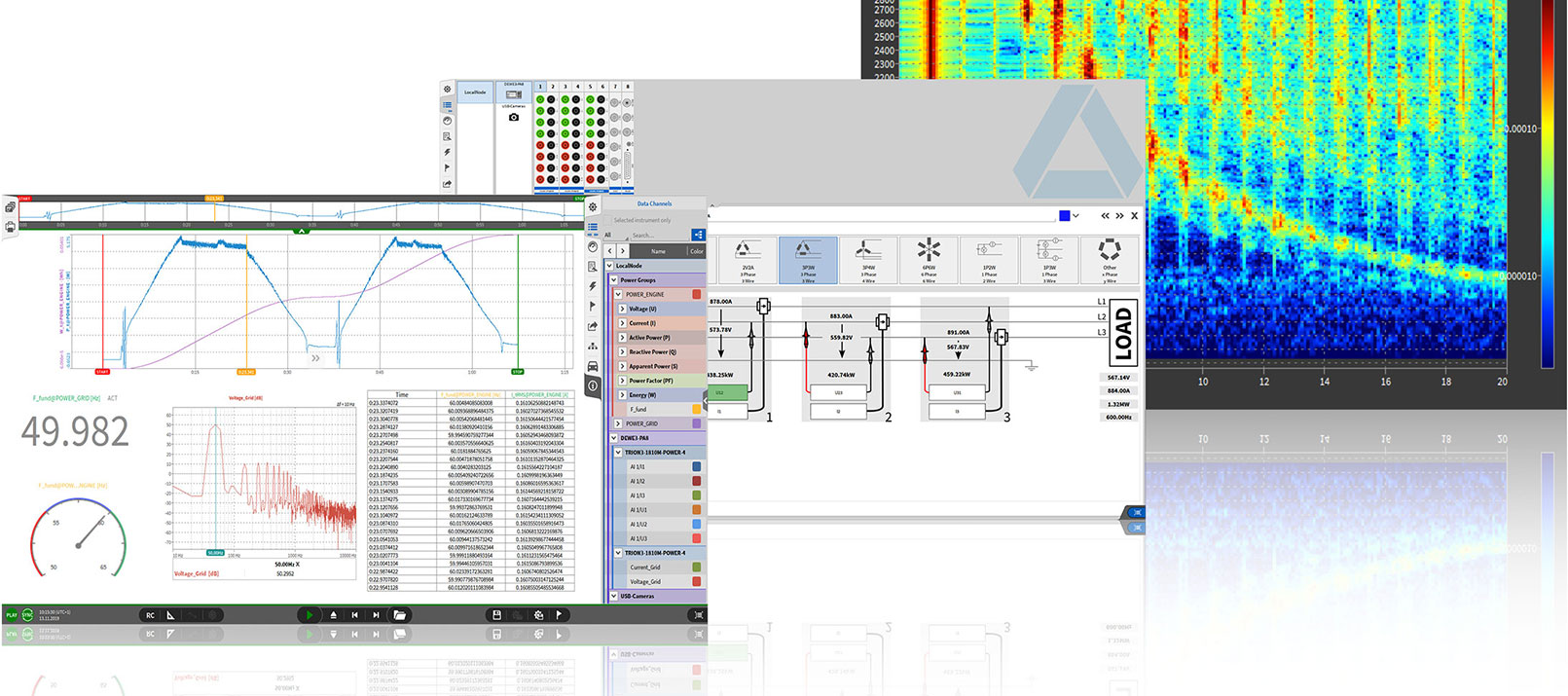
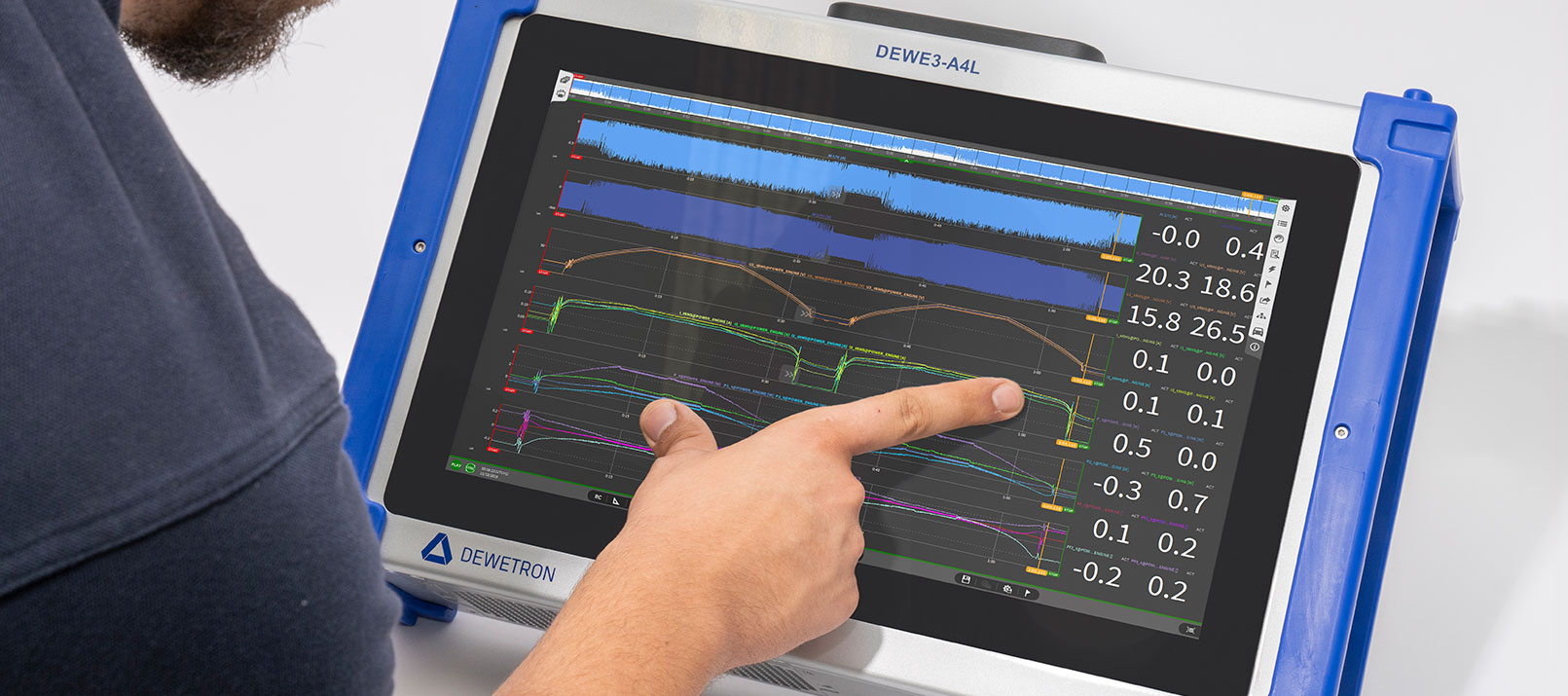
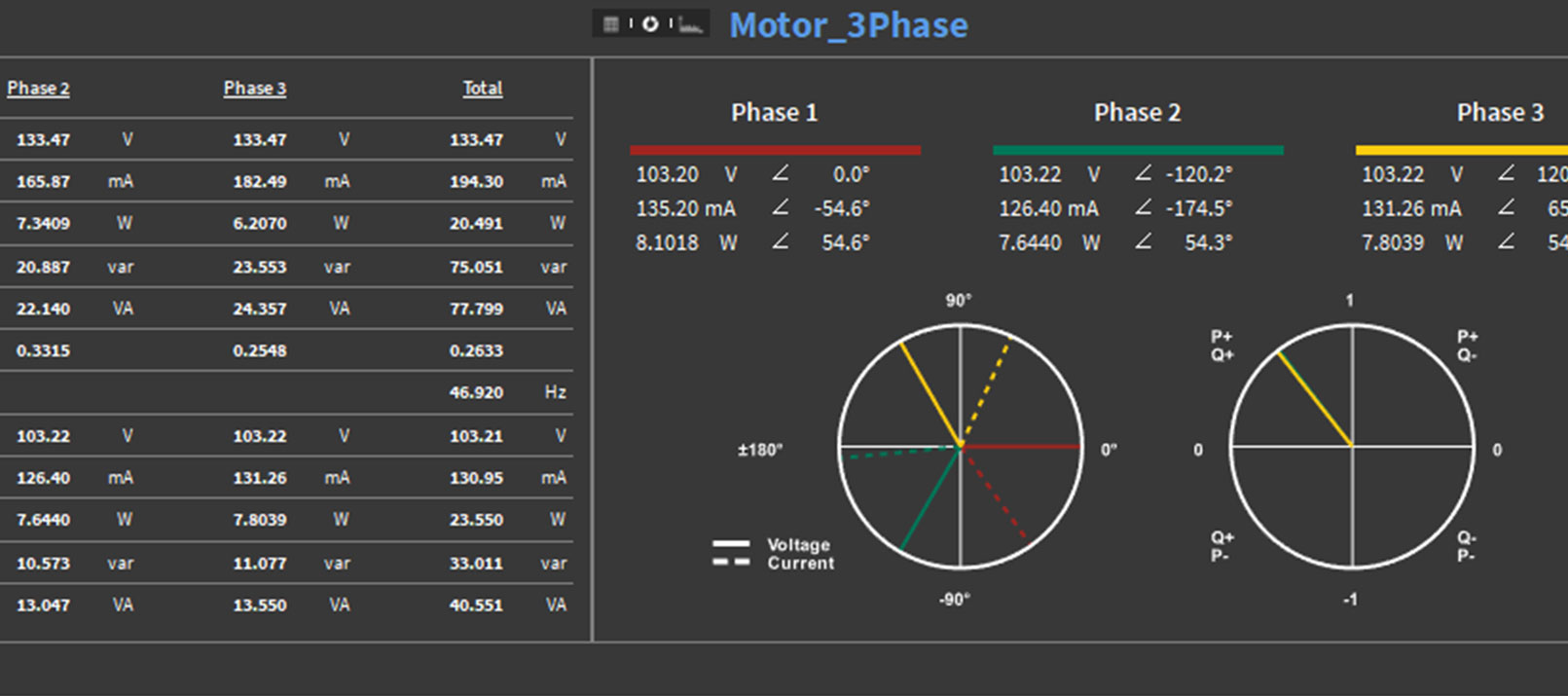
OXYGEN is our intuitive test and measurement software. It is an all-in-one software for measurement, visualization, and analysis for various applications. Therefore, it includes a huge variety of features, among others FIR filters.
It is an easy-to-use tool, which allows you to choose between four different filter types:
- Low pass
- High pass
- Bandpass
- Band stop
Once selected, simply enter the filter length, the desired window function, and whether or not you want to compensate for signal delay, and you’re ready to go. For a more detailed guide on how to set up an FIR filter in OXYGEN see our whitepaper.
In a nutshell
Digital filters are mathematical algorithms for manipulating signals to extract and/or remove unwanted information. FIR filters are a subclass whose impulse response is of finite length, as it settles to zero in finite time. In comparison to IIR filters, FIR filters are fundamentally more stable and can be designed to have a linear phase.