How do RPM & angle sensors work?
An RPM (revolutions per minute) and angle sensor is a device used to measure the motion, speed or angular position of a rotating object – usually a shaft, axel or disc. Such sensors are widely used, from small printers to big manufacturing machines, cars, aircraft and many more. But how exactly do they work?
To answer this question, we must first distinguish between the different types of sensors. There are several kinds based on various operating principles and physical effects. The two most common are optical sensors and magnetic sensors.
What are magnetic sensors?
Magnetic sensors themselves can be further divided into several different groups classified by their specific working principle. Among others, inductive sensors and TMR (tunnel magnetoresistance) sensors are commonly used.
What are inductive sensors?
An inductive sensor is a simple magnetic sensor based on the fundamentals of electrodynamics – the induction of a current due to changes in the magnetic field. In general, an inductive sensor consists of a core coil attached to a permanent magnet at one end of the coil. If a ferromagnetic piece then moves past the sensor close enough, the magnetic field in the coil will change inducing a current flow in the windings of the coil. This current or the corresponding voltage can then be measured.
Figure 1 shows a simplified schematic of this process using a ferromagnetic gear wheel. Each time a gear tooth bypasses the sensor, a current is induced and our measurement peaks. By the same token, the measurement is lowest when a gap is passing. Therefore, we obtain an oscillating signal, where a single oscillation represents one tooth and gap passing. Knowing the total number of tooths, it is then possible to calculate the time per revolution and hence also the revolutions per minute (RPM), the frequency, and the angular position.

Figure 1: Simplified representation of the operating principles of a magnetic sensor. The rotation of the ferromagnetic gear changes the magnetic field in the coil and induces a measurable current.
What are TMR sensors?
TMR sensors consist of two components: a magnet attached to a rotating object and a magnetoresistance (MR) sensor. The MR sensor itself is made of two ferromagnetic layers – the pin layer and the free layer – separated by an insulator. Even though the magnetic field of the pin layer is fixed, the magnetic field of the free layer can rotate and therefore changes according to the magnetic field of the external magnet.
The sensor must be placed at a certain distance from the magnet to allow interaction between the two magnetic fields. The sensor then measures the change in resistance of the applied magnetic field due to the influence of the external rotating magnetic field created by the spinning magnet. If both magnetic fields are aligned and therefore point in the same direction, the resistance is low. However, if the external field points in the opposite direction than the applied field, we measure a high resistance. Therefore, it is possible to acquire the period and angular position at any time.

Figure 2: Simplified representation of the operating principles of a TMR sensor. Due to the rotation of the magnet, the resistance of the sensing element changes with the rotation angle.
What are optical sensors?
Optical sensors measure the rotation of an object by measuring light which is reflected periodically from the object itself. For this purpose, an infrared (IR) laser usually sends light onto the spinning object. The object itself is marked with an adhesive tape or another similar reflective material which reflects the incident beam back to the sensor. To measure the reflected light, a photodiode is typically used to convert the absorbed light into measurable current. Every peak in the light intensity due to reflection, is paralleled by a peak in the electrical signal and thus allows to determine the frequency, period, rotational speed, and angular position.

Figure 3: Schematic representation of the operating principles of an optical RPM sensor. Illustration of the detection of an increased signal due to a stronger reflection on one singular strip of tape.
What is signal processing and angular positioning?
The before described optical and inductive sensors can be summarized as incremental encoders. The signals provided by these sensor elements (optical or magnetic), typically are converted into square-wave signals by threshold switches. The output pulses are transmitted to the evaluation electronics and counted. The resulting number of pulses counted per time interval represent the measure of change in position.
To obtain information about the direction of movement two slightly shifted sensors are used, which results in two asynchronous signals. From the sequence of the leading and trailing edge of the two signals, it is possible to determine the direction of movement. Finally, for the absolute determination of position, a zero pulse is implemented once per revolution to mark the start/end of a revolution.

Figure 4: Converted square-wave signals obtain from two slightly shifted sensors plus zero pulse. These measurements include everything needed for an absolute determination of position.
Optical sensors at DEWETRON
As already noted, RPM sensors are used in a wide range of machines. The intended purpose however always varies – sometimes it is only needed as additional information to other measurement channels and on other occasions, it may be needed for specific analyses. Depending on the application of the sensor, the mounting and installation are sometimes straightforward and sometimes not.
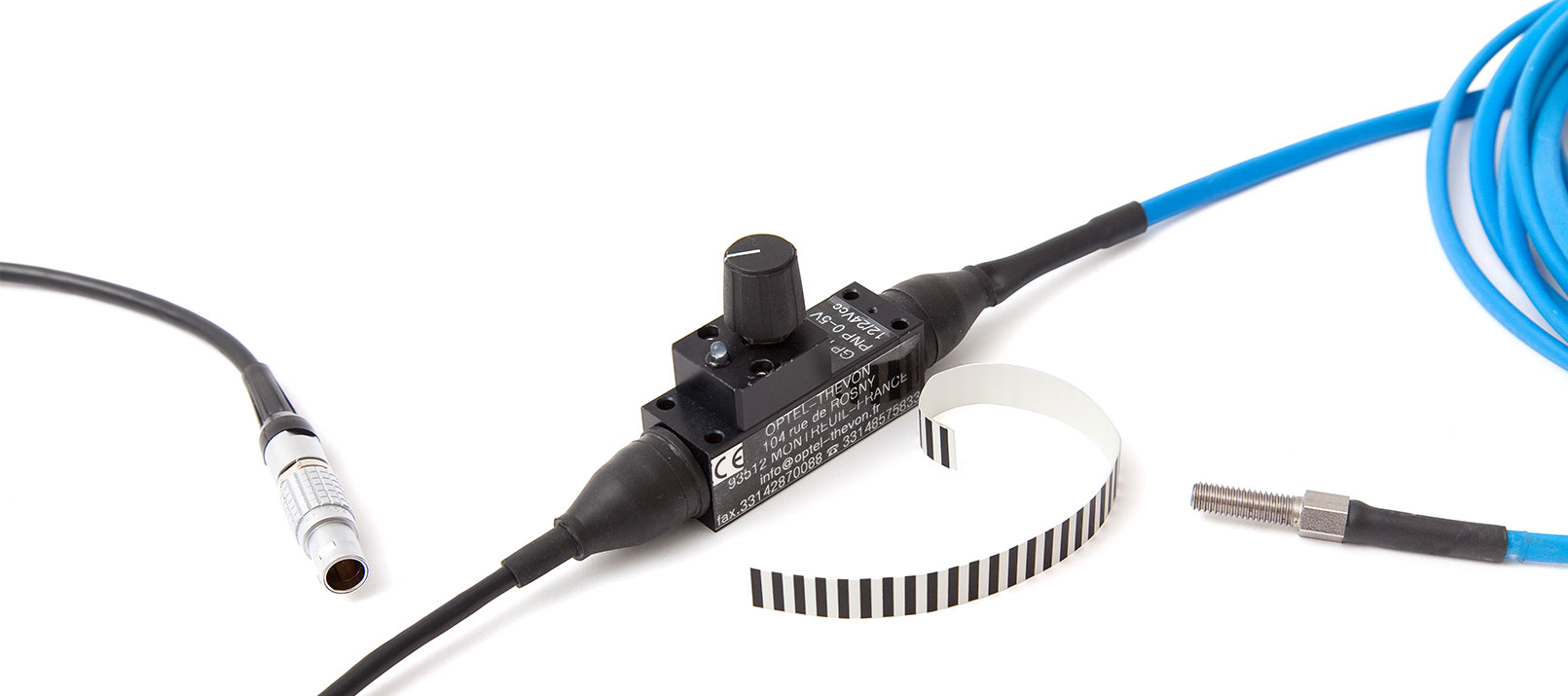
With our products – the TACHO PROBE and the TAPE SENSOR – we offer two easy-to-use and easy-to-install optical sensors for order tracking, field balancing, general RPM measurements as well as rotational and torsional vibration analysis. Both sensors are equipped with a LEMO connector and can be directly linked to a LEMO counter input of a DEWETRON measurement system. Besides the signal transmission, the LEMO counter input also provides the supply voltage – an additional power supply is therefore not needed.

Figure 5: Practical implementation of the DEWETRON Tape Sensor. The upper image shows the mounted sensor plus the reflective black and white tape attached to the rotating wheel. The lower image displays the measured and processed data via OXYGEN – DEWETRON’s intuitive measurement software.
Put in a nutshell, there are plenty of different RPM and angular sensors out there. Usually, they are based on either optical or electromagnetic effects. Whereof some have a more complex operating principle and implementation than others. We at DEWETRON provide you with two simple but effective optical sensors combined with a highly detailed measurement system for various practical applications.