The Measurable difference.

Dewetron blog news

the measurable difference

The DQ analysis for rotary field machines
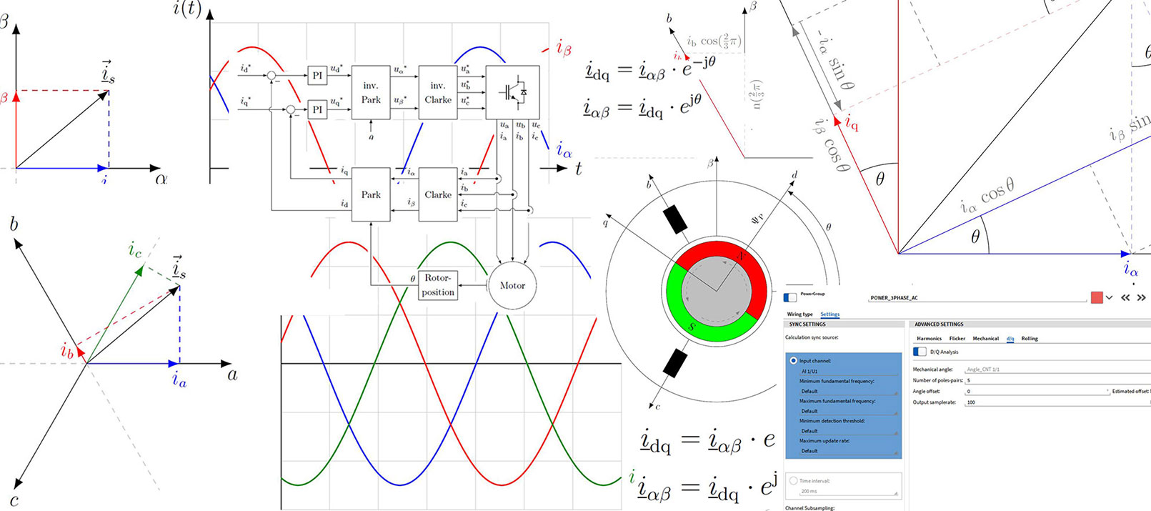
 || Whitepaper

17/10/2022 | Hardware, Whitepaper

Introduction

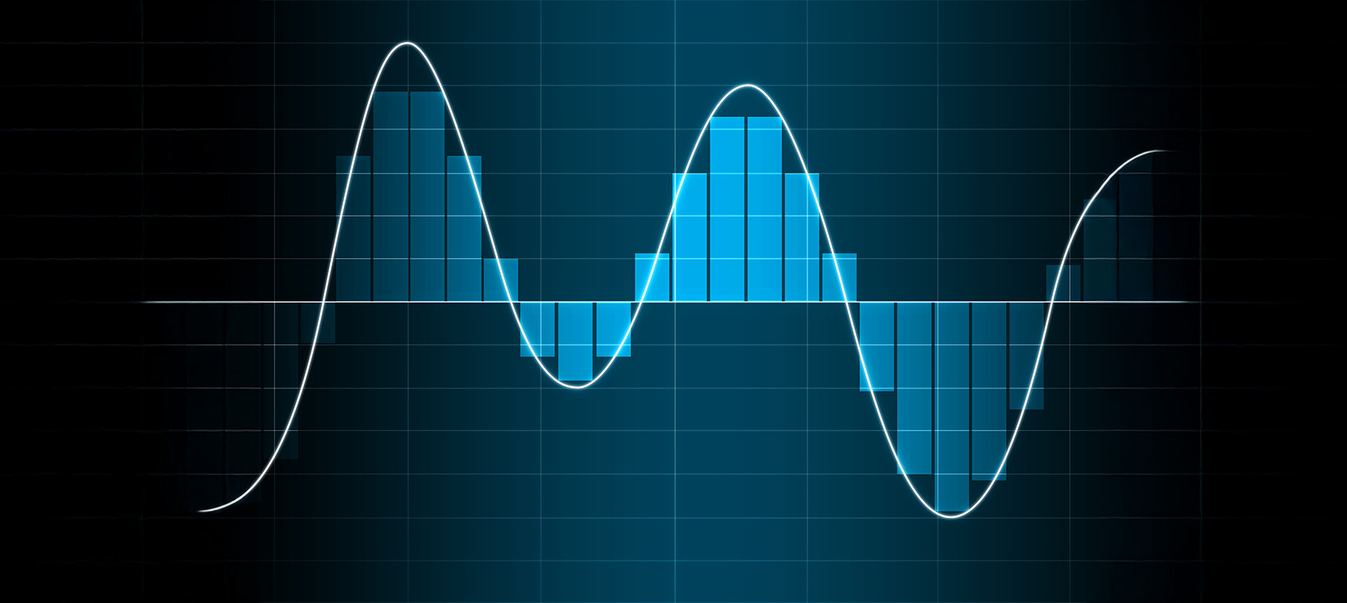
The DQ analysis is used to convert the occurring alternating quantities in rotating field machines, such as electric currents, induced voltages or flux linkages, into constant quantities. This offers advantages for the analysis and control of electrical machines.
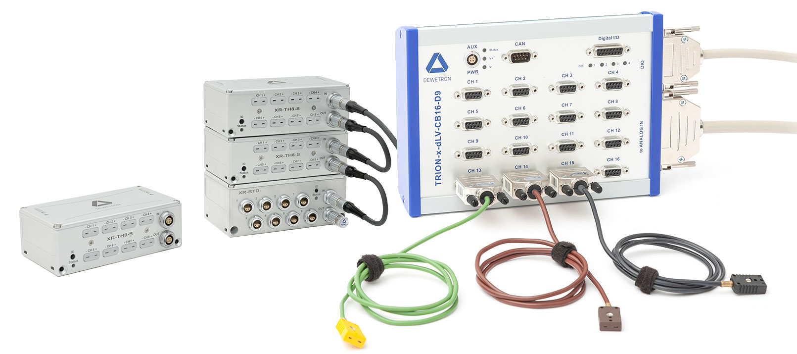
The direct axis (d-axis) and the quadrature axis (q-axis) of the associated coordinate system give the DQ analysis its name.

Fig. 1: Coordinate systems of a 2-pole synchronous machine

In the figure above, the coordinate systems relevant for rotating field machines are shown in the simplified cross-section of a synchronous machine. The following axes are shown:

  • a-, b- and c-axis of the abc- (or uvw-) coordinate system
  • α- and β-axis of the αβ-coordinate system
  • d- and q-axis of the dq-coordinate system

Also, the flux linkage of the rotor, the so-called field spider flux ΨP and the rotor angle θ are shown. The basic idea of the DQ analysis is to map the three-phase system of a rotating field machine, each with axes offset by 120°, to orthogonal, i.e. rightangled systems, with axes offset by 90°. This is accomplished via coordinate system transformations. With the Clarke transformation one obtains the αβ-coordinate system fixed to the stator. Rotating this coordinate system synchronously with the rotor, results in the dq-coordinate system fixed to the rotor. This rotation is done via the Park transformation. Before going into the mathematical details of these transformations, they are shown in an illustrative way in the following diagrams.

Fig. 2: The abc-coordinate system

Fig. 3: The αβ-coordinate system

Fig. 4: The dq-coordinate system

The splitting of the coordinate system oriented to the magnetic field of the rotor into a d- and q-axis enables a separate adjustment of the torque-forming quantity iq and the field-forming quantity id in the field-oriented control. A magnetic field along the d-axis generated by the windings of the stator strengthens or weakens the magnetic field created by the permanent magnets of the rotor and does not cause torque. This is utilized in what is called field weakening to achieve speeds that exceed the nominal speed range of the machine. A positive current iq produces a positive magnetic flux along the q-axis and thus a torque in the positive direction of rotation, i.e. counterclockwise. A negative current iq generates a torque in negative direction of rotation, i.e. clockwise.

CLARKE TRANSFORMATION

The Clarke transformation maps the 120° offset quantities of the machine in the uvw or abc coordinate system to two 90° offset quantities in the αβ-coordinate system. This transformation is also called the 3→2−transformation. The amplitude invariant Clarke transformation assuming a symmetric three-phase system can be represented as follows:

This conversion is reversible with the inverse Clarke transformation:

Fig. 5: Visualization of the Clarke transformation

After the Clarke transformation, the three quantities of the symmetric three-phase system are mapped to two alternating quantities in the stator-fixed αβ-coordinate system. If this coordinate system is rotated by the electric rotor angle θ, the rotor or rotating field-fixed dq-coordinate system is obtained by the Park transformation:

This operation is reversible with the inverse park transformation:

The dq-coordinate system rotates in the synchronous machine coupled to the rotor with the same electrical frequency as the rotating field. This results in constant quantities for the currents id and iq in steady-state operation. The Park transformation is graphically shown with the trigonometry used in the following diagram.

Fig. 6: Visualization of the Park transformation

This coordinate system has a direct or d-axis and a quadrature or q-axis oriented 90° offset to the d-axis. The d-axis points in the same direction as the pointer of the field spider flux ΨP.
In the Park transformation, [iα iβ]T is rotated by a rotation matrix. It is convenient to express the αβ → dq and dq → αβ conversions with the complex phasors iαβ = iα + j · iβ und idq = id + j · iq in an abbreviated complex representation:

If iα, iβ and id, iq are known, the electric rotor angle can be extracted from them.

The Park transformation and also the inverse Park transformation can be generally defined in the symmetric three-phase system without the intermediate step via the Clarke transformation:

All described coordinate system transformation sonly represent the quantities of the three-phase system in a different way. No information is lost during the transformations. Therefore, one can easily reverse the transformation with the corresponding inverse variant. Analogously, these transformations can also be applied to voltages and magnetic fluxes.

In steady-state operation, i.e. at constant torque and constant speed, the voltage and current waveforms in the dq-coordinate system result in DC quantities that allow a structure analogous to the control of a DC machine.

Fig. 7: Field-oriented control (FOC) of a rotating field machine

The information of the rotor position is necessary for the field-oriented control, because the rotating field must be adjusted depending on the rotor angle. This task is usually performed by position encoders. Due to the Park transformation, the reference quantities i*d and i*q are constant quantities in steady-state operation. Therefore, PI (proportional integral) controllers can be used for the control, as it is also usual for the DC machine. The inverse Park transformation then produces time-variant quantities necessary for the rotating field.

With the DEWETRON Power Analyzer, the DQ analysis can be achieved very easily to check the measured value against the set value from the machine controller.

Fig. 8: DQ analysis on the DEWETRON Power Analyzer


WHITEPAPER DOWNLOAD


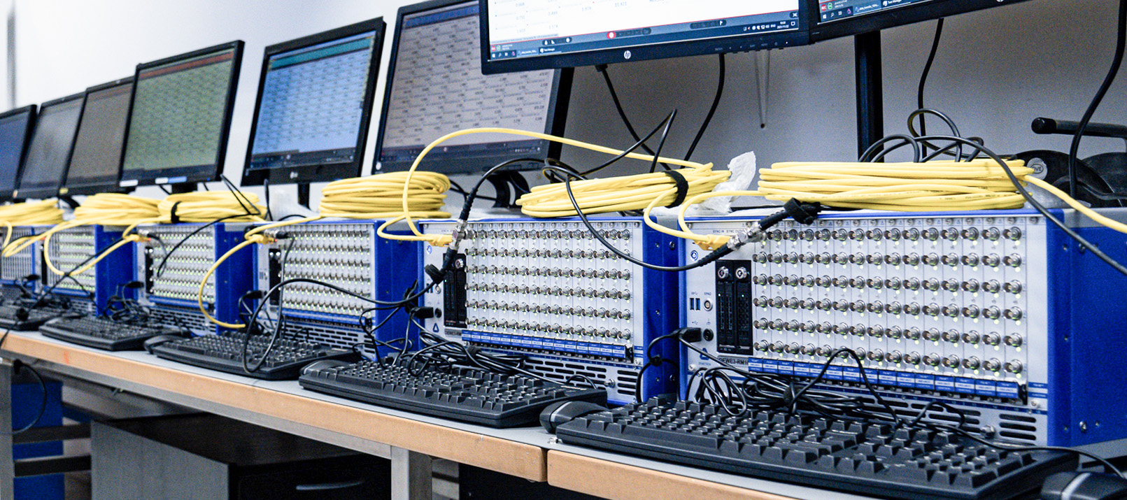
DEWETRON – Your expert in measurement technology

DEWETRON is a specialist in the field of measurement technology. The goal is to produce measuring equipment that meets the highest possible quality standards, is modular and versatile, as well as easy to use.
If you want to learn more about DEWETRON, you can visit our DEWETRON website. . There you will find further whitepapers as well as blogposts and video tutorials. We are also active on social media. Take a look at our Twitter, LinkedIn or YouTube pages.

Recent Posts

Contact us Contact us

Do you have a question?

Kontakt-Formular