How to measure current and voltage
Current and voltage are the most fundamental characteristics of an electrical circuit. Without knowledge of these quantities, it would not be possible to manufacture smartphones, televisions or even refrigerators. For this very reason, we want to return to the basics of electrical engineering and explain to you how to make current and voltage measurements.
The basics – parallel and series connection
In electrical engineering, there are two types of circuits: The parallel and series connections. You can see these two types of circuits here:

Parallel (left) and series (right) connection
Of course, you will now ask: What is the difference between parallel and series circuits and why is this important for current and voltage measurement?
In the series circuit, two components (in our case, two lamps) are connected to the power supply one after the other. The series connection’s characteristic is that the same current is present everywhere, no matter at which point you measure. This can be imagined to be like a water pipe: If water flows into the pipe at one end, the same amount of water must come out at the other end. The same water flow also prevails everywhere in the pipe.
However, the electrical voltage is not the same everywhere in the series circuit. Part of the voltage is lost at the first lamp (this is called a voltage drop), and a further part of the voltage is lost at the second lamp. The more components you connect in series, the less voltage is left for the last component.
In contrast, in a parallel circuit the voltage drop is the same for all components. The reason for this is the arrangement of the components: They are placed beside each other and not directly behind each other. But this also means that the current is not the same in the whole circuit. Here again the analogy to the water pipe is helpful. If the water pipe divides into two smaller pipes, only a part of the original total current flows through each pipe.
But now we have bothered you long enough with the basics. So how does current and voltage measurement work?
The current measurement
For the measurement of current and voltage one uses so-called ammeters and voltmeters. Devices that can measure current as well as voltage (and usually other quantities as well) are called multimeters or power analyzers.
If you want to measure the current, you connect the ammeter in a series to the components. Why in series? Because only then, as explained above, the same current flows through the ammeter and the component. If the ammeter were connected in parallel with the component, a different current would be measured.
At the same time, an ammeter must have a very low internal resistance. Due to this low internal resistance, the measuring device hardly influences the circuit. If the internal resistance were large, then (according to Ohm’s law) also less current would flow in the circuit. In this case, the measurement would influence the system. Because of this low internal resistance, it is again a very bad idea to use an ammeter in parallel. In this case a lot of current could flow through the ammeter. This overcurrent will trigger the internal overcurrent protection and at least the fuse will blow. The ammeter will then stop working until one replaces the fuse.

Ammeter in an electric circuit
However, it is not always possible to open a circuit in order to install an ammeter. In these cases, indirect current measurement is advantageous. This means that you do not measure the current itself, but rather the accompanying effects of the current flow. From this, the electric current can be calculated. An example of an indirect current measurement device is the current clamp. It measures the magnetic field produced by the current and thus deduces the current flow in the conductor. You can find a blogpost about current clamps here.
The voltage measurement
The voltage measurement works exactly the other way round to the current measurement. A voltage meter (voltmeter) is connected in parallel to the component where the voltage drop is to be measured. Parallel because in a parallel circuit the same voltage prevails in both branches. You can also think about what would happen if you install the meter incorrectly, e.g. in series connection. In this case, a voltage would drop at the meter itself and the measurement result would be wrong.
For accurate voltage measurement, a voltmeter must have a very high internal resistance. This resistance should preferably be much higher than the resistance of the component over which you want to measure the voltage drop. This is necessary because otherwise the current flow in the circuit and thus the voltage drop across the component would change. In this case, the voltmeter would therefore have a direct influence on the circuit current.

Voltmeter in an electric circuit
Indirect measurement of current is possible and also very common, but there is no possibility for indirect voltage measurement. However, it is possible to measure voltage without contact by means of electrometers and similar measuring devices. However, one uses these methods rarely in the field of electrical engineering.
Current and voltage measurement with highest precision – DEWETRON
No ammeter, voltmeter or multimeter is perfect. Each of these measuring devices has a measurement error that can vary depending on the application and type of device. The measurement inaccuracy depends, for example, on the frequency of the AC voltage or on the resolution (stated in bits) of the instrument. The magnitude of the voltage and current can also cause problems. Many measuring devices have a limited measuring range and lose accuracy just at the edge of this measuring range.
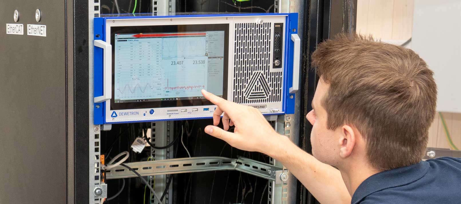
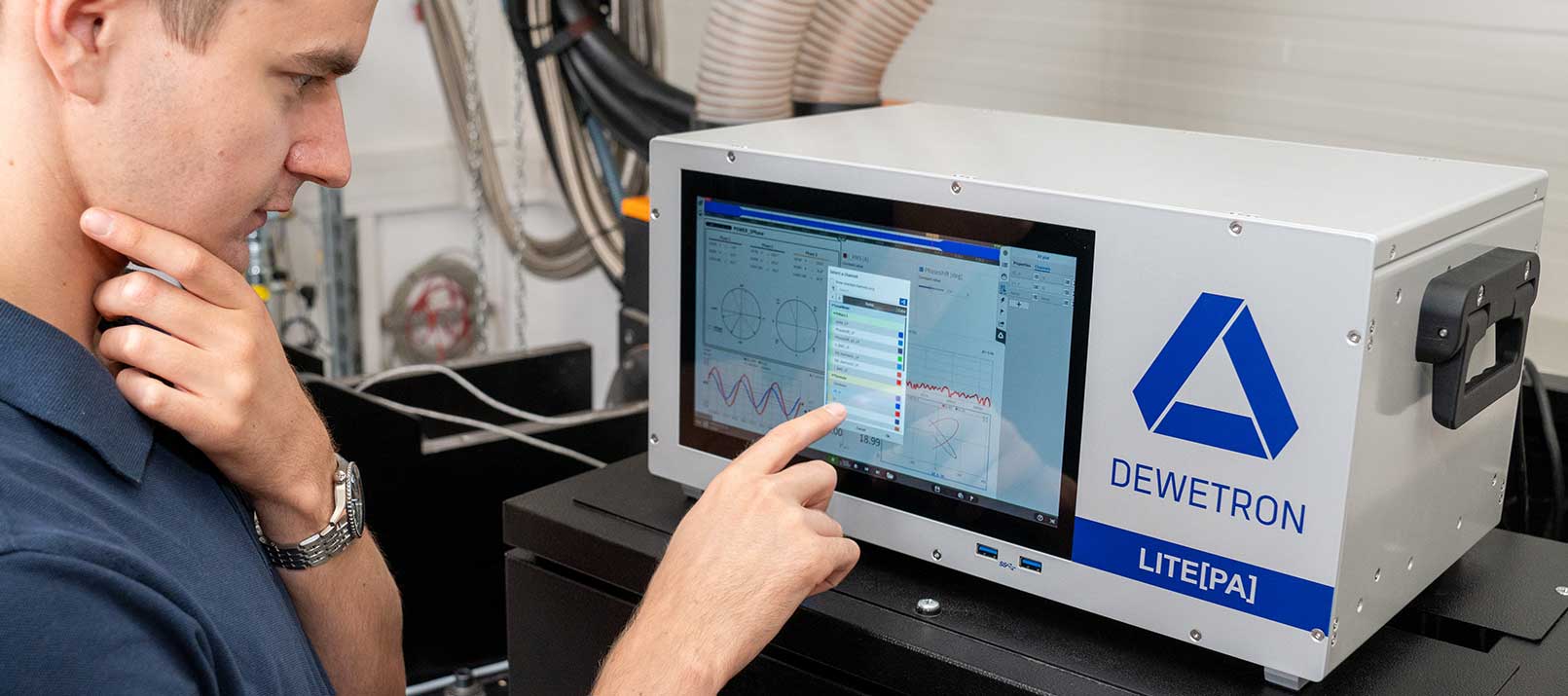
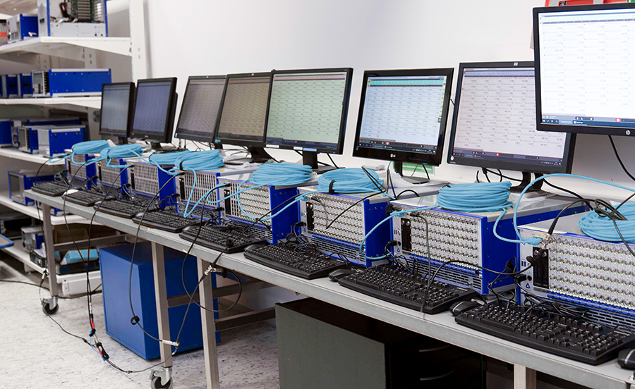
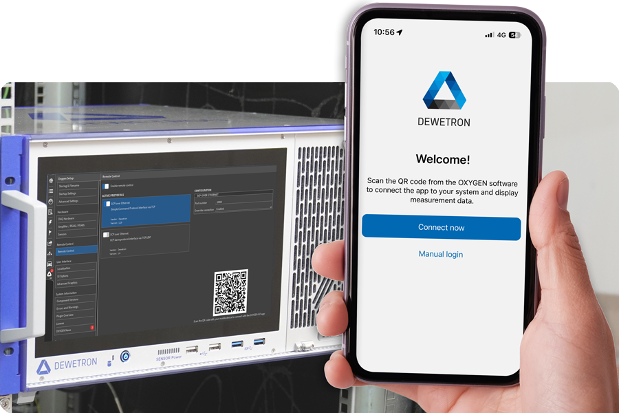
DEWETRON is a manufacturer of high-precision measuring instruments with headquarter in Austria and deals with exactly these sorts of problems. We manufacture a range of measuring instruments which stand out due to their superior accuracy. For example, our Mixed Signal Power Analyzer has a measurement error of less than 0.03%. Combined with a resolution of up to 18 bits and a sampling rate of 10,000 kS/s, this power analyzer is perfectly suited for precise current and voltage analysis.
In addition, our proprietary OXYGEN measurement software, which is pre-installed on every DEWETRON system, makes measurement easy. Simply connect your meter to the circuit and the rest is a breeze. For example, you can customize your own measurement screen – exactly as it best suits your needs.