How do current transducer work?
Nowadays, the accurate measurement of electrical currents is a fundamental cornerstone for ensuring the efficiency, safety, and reliability of systems. Whether in the field of electrical engineering, industrial automation, renewable energy, or many other areas, current measurements are necessary everywhere. There exists an arsenal of tools for sensing and measuring currents, and in today’s blog post, we have a closer look at current transducers.
How do current transducers work?
The exact working principle depends on the type of current transducer used. However, the most common type is the inductive current transformer which is mainly used for converting alternating currents. Overall, the operating principle closely resembles that of a classical transformer (Fig. 1: left schematic). In the following steps the working principle of an inductive current transformer (Fig. 1: right schematic) is described:
-
- A magnetically good conducting material connects two circuits, the primary and secondary circuit. This material is often a ferromagnetic ceramic, a so-called ferrite. The primary and secondary circuits are then spirally wound around the ferrite. However, there are also designs in which the primary circuit only consists of one cable running through the center of the ferrite.
- The alternating current to be measured flows in the primary circuit but is too high for the ammeter. According to Amperè’s law, this alternating current generates a magnetic field which, like the alternating current, constantly changes its polarity.
- The magnetic field mentioned is bound in the ferrite because ferrites are magnetic conductors. It is therefore also present in the secondary circuit. According to another physical law, the law of induction, this changing magnetic field generates a current in the secondary circuit. In the case of a current transducer, this secondary current is smaller than the primary current.
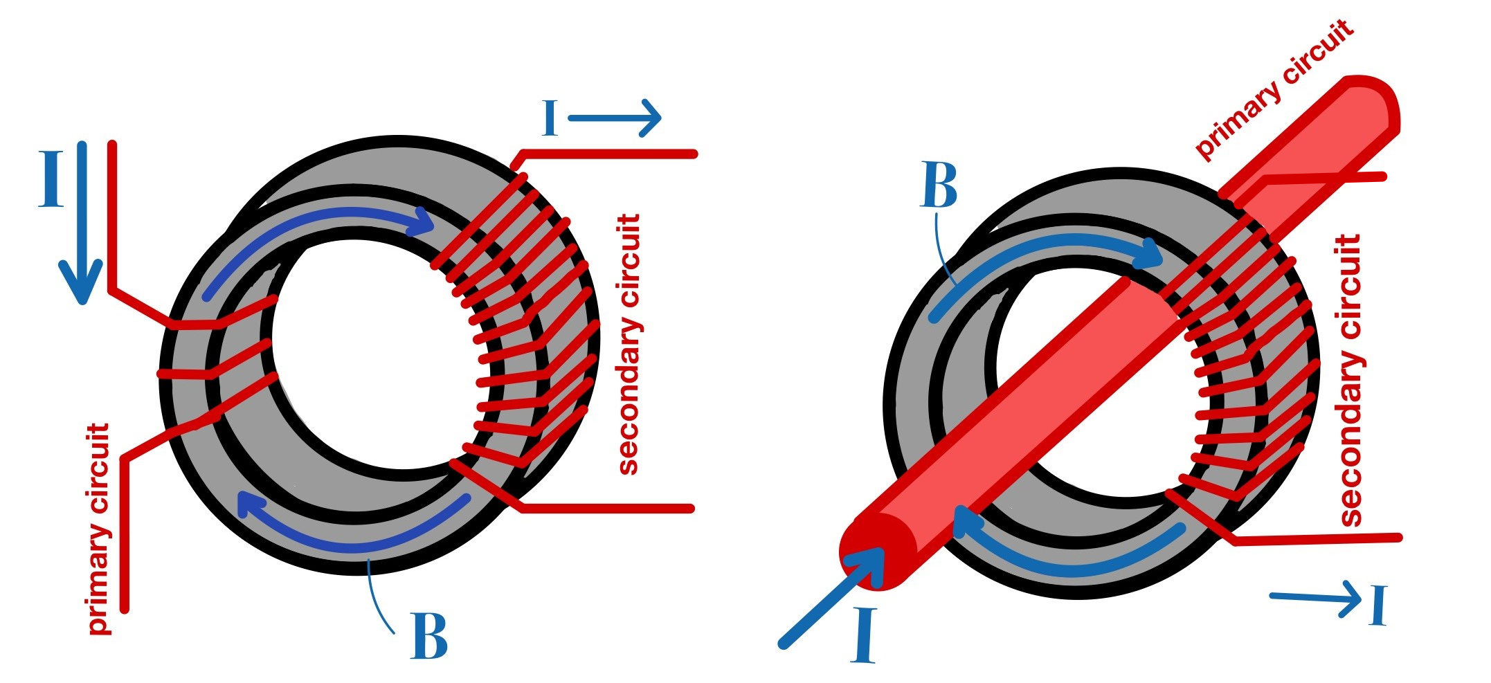
Figure 1: Schematic view of a classical transformer (left) and current transducer (right).
If one looks more closely at the underlying physical equations, it is possible to determine the conversion ratio.

The conversion ratio indicates how much the current is reduced by the current transducer and corresponds to the number of windings (N) of the primary and secondary circuits (N_primary/N_secondary).
Note: There are further possibilities to realize a current transducer. As an example, well-known constructions are based on Hall probes or Rogowski coils.
Is there a distinction between a current transducer and a current transformer?
Although the terms “current transformer” and “current transformer” are often used interchangeably, in theory, there are some subtle differences. A transformer’s primary function is to alter an electric current to a different level, either stepping it up or down depending on the application. An illustration of a typical transformer build is shown on the left side of Fig. 1. On the other hand, a transducer is primarily used to measure electric current. It converts the electrical current into a format that enables simple recording, usually a voltage signal. An example of a transducer is shown on the right-hand side of Fig. 1.
Imperfections of real current transducers
Real current transducers, like any physical device, will suffer from imperfections. The two most important error variables that you should keep in mind are:
1. Transformation error:
The real conversion ratio can deviate from the ideal ratio due to various factors inherent in the theoretical idealization. These factors include assumptions such as a linear magnetic circuit with infinite permeability and negligible resistance in the windings. Additionally, material irregularities can also contribute to deviations.
The transformation error is typically expressed as a percentage of the measured value. The left graph in Fig. 2 shows the transformation error across a range of frequencies for AC signals. The green and blue lines represent different devices.
Example: When measuring a 20 ampere AC signal at 30 kHz with a CT 100, the transformation error is 0.5000%. Consequently, the final outcome would be adjusted to 19.9 amps to account for this error.
2. Angle error:
The phase between the primary and secondary currents can also deviate. The main reason for this is the electronic runtime within the device. The angle error (also called angular accuracy or phase error) expresses the difference of this phase in units of degrees. The right graph in Fig. 2 shows the angle error in degrees along a range of frequencies. The green and blue lines indicate different devices.
Note: The angle error is especially important in active power calculation. To ensure accurate results, compensation for phase angle error is essential.

Fig. 2: Transformation error (left) and angle error (right) of SIGNALTEC CT 100 and CT 1000.
Why do we need current transducers?
In real-world scenarios, accurately measuring electrical currents within components or power cables is often necessary. Standard ammeters typically have limitations, often unable to measure beyond a few tens of amperes. While this is sufficient for many applications it is easy to imagine scenarios where the currents are significantly higher:
- Electric motors (approx. 150 A)
- Railroad overhead lines (approx. 1000 A)
- Generator currents in power plants (several kA)
For these high current requirements, a current transducer can be used, which converts a high input current into a smaller, yet proportionate output current. For instance, a 1000 A input current can be transformed into a more manageable 2 A output current. The conversion is based on a proportionality factor or conversion ratio, calculated as the input current divided by the output current. In this case, the proportionality factor is 500.
In addition to measuring applications, current transformers serve various other functions. They are used in control technology and in protection systems where the reduced current is conducted to Residual Current Devices (RCDs) or control devices that are not designed for high currents.
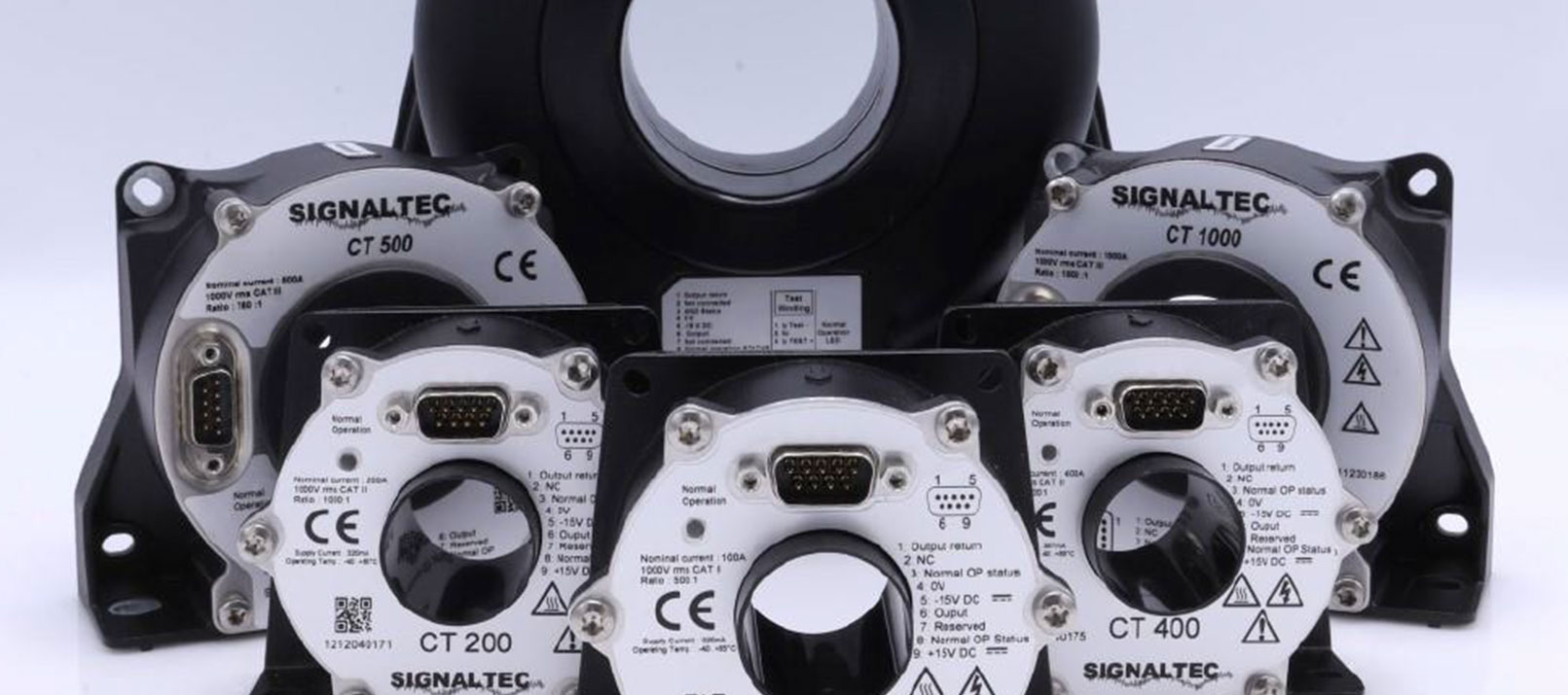
Current transducers at DEWETRON
DEWETRON’s data acquisition systems enable a wide range of measurements, also including current measurements. Easily integrated with high-precision current transformers from SIGNALTEC, these systems offer optimal solutions for a wide range of tasks. With conversion ratios of up to 2000 A/A, along with conversion errors as low as 0.0012% and error angles of less than 0.01°, SIGNALTEC transducers ensure high-end accuracy. In combination with synchronous voltage, temperature, or other measurements with our OXYGEN measurement software, DEWETRON offers an ideal solution for various applications. From simple system monitoring to comprehensive energy and power analysis, DEWETRON offers unmatched flexibility and performance.
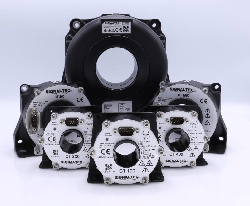
Figure 3: SIGNALTEC Current Transducers
If you would like to learn more about DEWETRON and our application areas, please feel free to visit our website. There you will find video tutorials, whitepapers, and webinars. You may also want to subscribe to our monthly newsletter.
